Before moving to the United States for my PhD study, which turned out to be an adventure of doing mathematics and neuroscience in a school of aerospace engineering,
I was a quite hands-on engineer.
Below are some stories about some of the engineering projects I worked on.
|
|
Design and Construction of an Intelligent Magnetic-Flux-Leackage Pipeline Inspection Gauge |
|
This was a relatively big (over $1M) project, funded by the National Iranian Gas Company,
which was done jointly by our group at the University of Tehran and a group of engineers at Segal Tech engineering company.
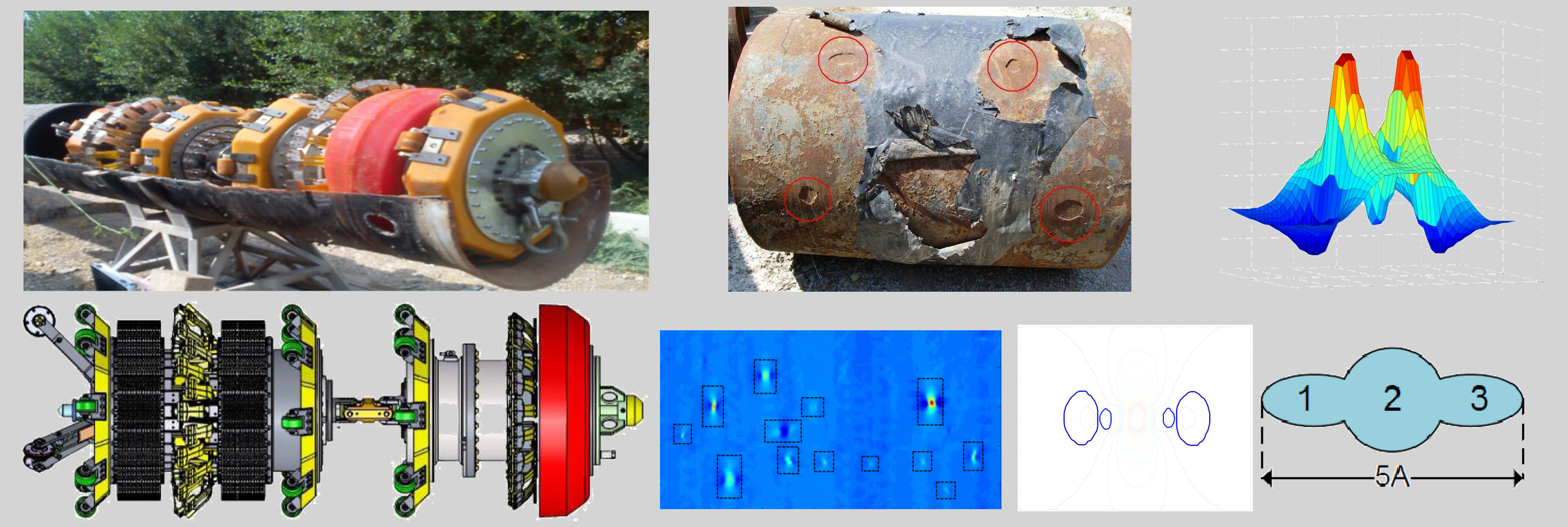
It aimed to design and construct a magnetic-flux-leakage (MFL) pipeline inspection gauge (PIG) for 60-inch natural gas pipelines.
The picture shown above is the PIG constructed by our collaborators at Segal Tech Co.
A key part of the project was developing data analysis algorithms for analyzing the data collected by the PIG, which was what we performed in our group.
I worked as the principal contributor and project coordinator of this data analysis part of the project for about one year, until the very last week before I left Iran.
The project was completed later on by my colleagues, and the PIG was successfully tested in a natural gas pipeline in Iran.
Natural gas pipelines must be regularly inspected for possible defects (corrosions, dents, etc.) and their severity.
These are often relatively expensive inspections.
A PIG is a device that is driven inside a pipeline by the pressure of the natural gas flowing through the pipe, at a speed ranging from 1 to 10 m/s.
An MFL PIG uses an array of very strong permanent magnets to magnetize a section of the pipe's wall up to its saturation level (about 1.8 T).
If the thickness of the wall is reduced at some locations due to a metal-loss anomaly, the magnetic flux leaks out of the wall
at the locations of the anomalies.
The radial and axial components of such magnetic flux leakages are then measured by some sensors, being arranged as a ring array covering the entire cross section of the pipe.
The profile of the measured flux leakage from an anomaly is then used to estimate the effective length, width, and depth of the anomaly, and subsequently its level of severity.
The accuracy of the estimated geometry must satisfy certain standards of the industry.
We created a database of MFL measurements, both by simulating a variety of defects in COMSOL Multiphysics® and
by collecting data from natural defects in a test pilot using the PIG our collaborators had constructed.
We used the database to develop algorithms (using tools such as support vector regression) for estimating the geometry of an unknown defect based on its measured MFL signals.
There were many practical factors that made the project challenging, as the profile of a real MFL signal measured during pigging could
be affected by several sources of perturbation and uncertainty, such as unknown orientation of defects relative to the direction of magnetic field lines,
changes in the distance between the sensors and the pipe's wall during pigging,
changes in the magnetization level of the wall due to inhomogeneities in the wall's metal,
changes in the wall's thickness,
changes in the travelling speed of the PIG, etc.
Of course, there are always such practical challenges that make engineering projects interesting.
|
|
Functional Description of the Automation System of an Iron Direct Reduction Plant |
|
I worked for about one year as a project coordinator and principal contributor for an industrial automation and instrumentation company.
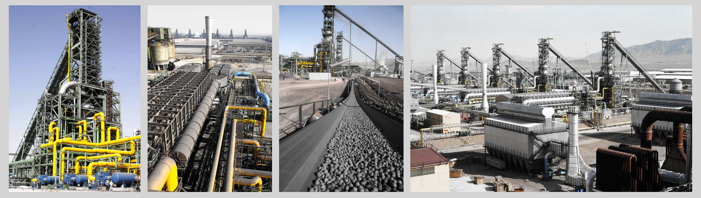
The project I coordinated and worked on aimed to develop a Functional Description document for the entire automation system of
a direct reduction plant in Mobarakeh Steel Complex, as well as Cause & Effect diagrams for the alarming and safety of the system.
A Functional Description document is one of the basic documents that are developed to be used for implementing the automation system
of a large processing plant. It provides an overview of the entire processing sequences and describes in words the details
of every single automation and control considerations:
how the loading and speed of conveyers involved in the material handling system is controlled,
how the pressure of gas compressors is controlled and their safety and cooling system operates,
how the flow and temperature of gas across reformers is controlled,
how the flow of material and reduction gas into the furnace is controlled, etc.
This document also serves as a reference for plant operation engineers for future troubleshooting of the automation system.
Cause & Effect diagrams are documents that list all safety alarms and interlocks.
These diagrams serve as references for plant engineers
to immediately identify causes of alarms and safety shutdowns that may occur during the operation of the plant.
Developing from scratch a Functional Description for a newly constructed plant of the size we worked on is a very expensive project.
Our job was different though. The automation system of the plant was designed and implemented by a Japanese company several decades ago.
But the functional description of the system was not available. Only old logic diagrams and P&ID diagrams were available.
We used those documents and consulted with the experienced engineers of the plant to figure out how everything was designed.
Then we wrote a functional description that could be used as a reference for future renovations of the system.
I was happy that what we finally accomplished brought our company enough profits to pay all the salaries in our engineering department,
which had been delayed for several months due to funding deficiency.
|
|
Reverse Engineering a DSP Starter Board |
|
This was my favorite project, and one of the neatest projects I have ever done entirely on my own.
I enjoyed all my time working on this project, back in 2007, when I had just received my master's degree in electrical engineering/control systems.
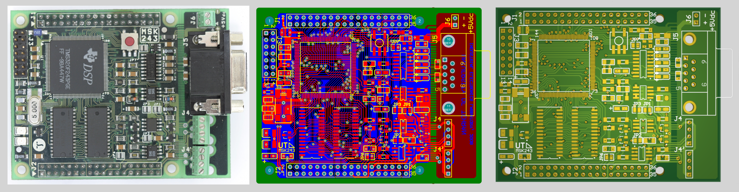
The electronic board shown in the left picture was a 4-layer commercial DSP starter board produced by a company in Switzerland.
We had used it to implement the control system of a relatively expensive low frequency heating project in our industrial electronics lab.
The board had to work in proximity to a high current (in kA range) circuit.
As a result, many of the backup boards we had purchased had got damaged by electric shocks during the tests of the heating system.
And, the manufacturer had discontinued producing this model of the board!
Replacing the board with a new model was a nightmare, as it required rewriting the programs and re-designing a large number of other circuits.
I took the challenge to reverse engineer the board and make backup copies for our project.
That had to be done without touching the original boards we had, because only a couple of them were left.
I identified the components, figured out the functions of each unit,
redesigned the whole circuit, implemented the circuit schematics in Altium Designer,
made the PCB layout, ordered the PCB from a manufacturer in another country,
purchased all the electronic components or their equivalent available in the market,
soldered them on the board, and tested the result.
I had to read a couple of chapters of a book in electromagnetic compatibility to figure out that some parts of the board were in fact
implemented for EMC compliancy purposes and didn't have a direct role in the functionality of the board.
The cost of the PCBs and their shipment from another country was relatively high for our lab.
So, I had to be as careful as possible so that hopefully the first version of the board I made would work.
And yes! a neat project is a project that works perfectly in the first test!
I made ten copies of the board. I was paid a total of $900 for my whole work on this project.
I added about $200 more to it and could buy my first laptop.
The laptop rewarded my hard work though.
It worked for me for about 15 years!
I still have it. Half of its screen sadly died recently, but it is still a good old friend :)
|
|
Undergraduate Robotic Projects |
|
I and two of my best friends skipped many classes during our undergraduate study to build robots to win robotic competitions!
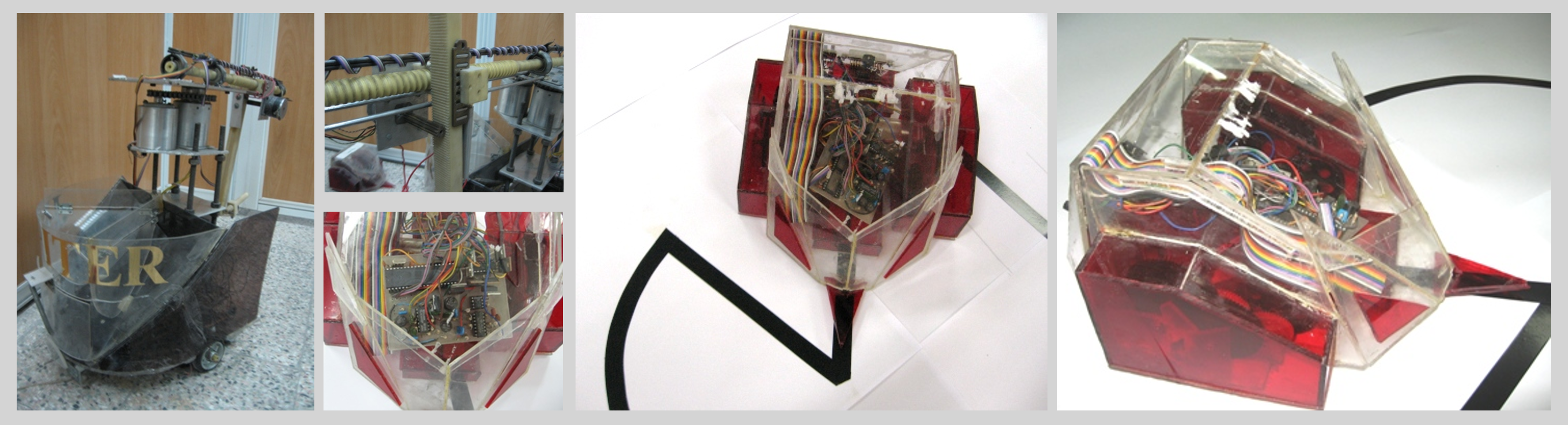
The picture shown above on the left is what was left from one of the robots we built,
after removing its camera, laser pointers, gripper, and motors. We worked on this robot for about six months,
as a team composed of four electrical engineering students, four mechanical engineering students,
and one computer engineering student. The robot was supposed to collect objects of three different types,
tennis balls, soap boxes, and soda cans, which were randomly located on a 2m x 2m table.
There was one location at which the objects were sitting on top of each other.
After collecting the objects, the robot was supposed to deposit them into three separate baskets.
Objects of the same type had to be in the same basket. This was the task defined as the advanced level of our nationwide robotic competition, back in 2002.
Two of us, including me, were responsible for developing the image processing algorithms for the robot's vision.
We had only one camera, so we had augmented it with an array of laser pointers so that we could accurately estimate the position of the objects relative to the robot
and guide the robot's arm to those positions.
I set my life-time record of losing sleep in the last week before the competition day (sleeping only a total of 8-10 hours in five consecutive days),
helping my friends to complete the mechanical parts. We couldn't finish it though :(
The line-tracker mouse shown in the other pictures worked perfectly.
It won us the first place in our schools' competition.
The key factor resulting in its high performance was the good simulation program we had written to optimize the number and position of its sensors,
so that it could track almost any lines with any curvature.
What made our job challenging, and fun, was that at that time we didn't have access to many of the components we needed.
We had to build the gearboxes by putting together gears taken from old VHS tape players! We made the sensors from the infrared diodes used in TV remote controllers.
Things changed a lot a few years after, when building robots of that kind had become popular in schools.
Specialized components were easily available in the market.
I made an easy-to-assemble version of the robot and used it to teach summer robotics classes to middle school and high school students.
They could assemble the mechanical parts, solder the electronic components and build the circuit, program the robot's microcontroller, test it, and enjoy.
I was also really enjoying my time teaching them.
|
|
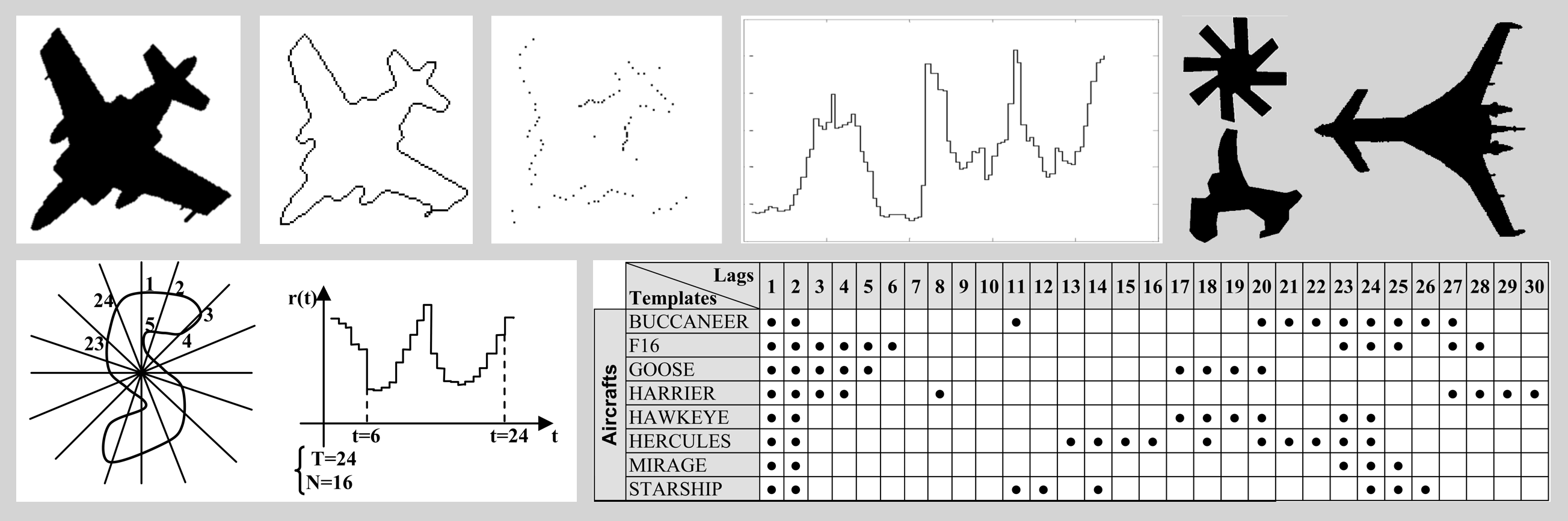
2-Dimensional Shape Classification |
|
This was the course project
I did in a graduate-level Pattern Recognition course that I took when I was an undergraduate student.
I am posting it here so that some of the students of my classes who complain about their course load can see how a course project could look like in the past.
They may start feeling happy they were not a student at that time!
Of course at that time there was no AI to assist students, not much sample code available in the internet, and no collaboration permitted.
In fact, I remember I even didn't have access to the electronic copy of the reference papers I used!
I luckily found the hard copy of the journals in the library of another university in our city.
|
|